
- #Cisco 2950 switch configure vlan how to
- #Cisco 2950 switch configure vlan software
- #Cisco 2950 switch configure vlan series
For example, for servers, the default gateway is 10.1.3.1.

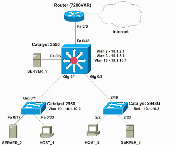
The default gateway configuration on each server and host device must be the VLAN interface IP address that corresponds on the 3550. These VLANs are the three VLANs that the user defines: In order to make the switch function as an 元 device and provide interVLAN routing, you must enable IP routing globally. By default, the Catalyst 3550 switch acts as an L2 device with disablement of IP routing. In this diagram, a small sample network with the Catalyst 3550 provides interVLAN routing between the various segments. Note: Use the Command Lookup Tool ( registered customers only) to find more information on the commands used in this document. In this section, you are presented with the information to configure the features described in this document.
#Cisco 2950 switch configure vlan how to
How To Configure InterVLAN Routing On Layer 3 Switches Configure
#Cisco 2950 switch configure vlan series
Here is a link to a video (available on Cisco Support Community ) that demonstrates how to configure the InterVLAN routing on a Catalyst 3550 series switch: In order to use this feature, you must have the IP services image, formerly known as the enhanced multilayer image (EMI), installed on your switch. You can forward these non-IP packets with fallback bridging. The switch does not route non-IP packets between VLANs and routed ports. In the example in this document, you can use access lists to restrict the engineering VLAN from access to devices on the finance VLAN. The design allows the administrator to restrict communication between VLANs with use of access lists. Such a VLAN design also has an additional benefit. If you enable routing, the devices in each VLAN can talk to one another without the need for all the devices to be in the same broadcast domain. For example, the engineering VLAN only has devices that relate to the engineering department, and the finance VLAN only has devices that relate to finance. The switch receives a packet, determines that the packet belongs to another VLAN, and sends the packet to the appropriate port on the other VLAN.Ī typical network design segments the network based on the group or function to which the device belongs. A new breed of switches incorporate routing capability within the switch. The device is either external to the switch or in another module on the same chassis. L2-only switches require an 元 routing device. Devices in separate VLANs require a routing device to communicate with one another. Devices within a VLAN can communicate with each other without the need for routing. In a switched network, VLANs separate devices into different collision domains and Layer 3 (元) subnets. Refer to Cisco Technical Tips Conventions for more information on document conventions.
#Cisco 2950 switch configure vlan software
This configuration can also be used with these hardware and software versions:Īny Catalyst 3750/3560/3550 switch that runs EMI software or standard multilayer image (SMI) Cisco IOS Software Release 12.1(11)EA1 and laterĪny Catalyst 2900XL/3500XL/2950/3550 or CatOS switch model, used as the access layer switch If your network is live, make sure that you understand the potential impact of any command. All of the devices used in this document started with a cleared (default) configuration. The information in this document was created from the devices in a specific lab environment. Note: The configuration from the Cisco 7200VXR is not relevant, so this document does not show the configuration.

The information in this document is based on these software and hardware versions:Ĭatalyst 3550-48 that runs Cisco IOS® Software Release 12.1(12c)EA1 EMIĬatalyst 2950G-48 that runs Cisco IOS Software Release 12.1(12c)EA1 EIĬatalyst 2948G that runs Catalyst OS (CatOS) version 6.3(10) Prerequisites RequirementsĮnsure that you meet these requirements before you attempt this configuration:įor more information, refer to Creating Ethernet VLANs on Catalyst Switches.įor more information, refer to the Configuring VLAN Trunks section of Configuring VLANs. You can substitute a firewall or other routers for the Cisco 7200VXR router. The Catalyst 3550 configuration also has a default route for all traffic that goes to the Internet when the next hop points to a Cisco 7200VXR router.

The document uses a Catalyst 2950 series switch and a Catalyst 2948G switch as Layer 2 (L2) closet switches that connect to the Catalyst 3550. The document provides a sample configuration for interVLAN routing with a Catalyst 3550 series switch that runs enhanced multilayer image (EMI) software in a typical network scenario. This document explains how to configure interVLAN routing with Cisco Catalyst 3750/3560/3550 series switches.


 0 kommentar(er)
